by Type_R
OBAVEZNO PROCITATI
Kako radi EEC IV
Ko zeli moze pogledati originalan tekst sa slikama na
http://www.rs20004x4.co.uk - EEC IV INFO
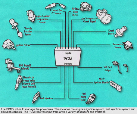
Hidden behind the passenger side kick panel of your Escort is the core of your car's performance capabilities - the Ford Electronic Engine Control version Four . Using an array of sensors, the EEC IV manages all aspects of your engine's operations from cold starting to Wide Open Throttle. These sensors monitor things like Manifold Pressure, Coolant Temperature, Air Temperature, Exhaust Oxygen content, throttle position, and many other atmospheric and driver input parameters affecting the engine's performance.
One of the many other capabilities of the EEC-IV is its ability to diagnose a poorly running engine. Through the use of self-contained sensor tests the EEC-IV can provide information about failed sensors, or sensors picking up abnormal operating conditions which can cause your car to perform poorly. In addition to these tests, the EEC IV can also perform cylinder balance checks informing you of individual cylinders which may be experiencing a drop in compression
Basic components
1. Electronic control unit (ECU)
An ECU is a self contained custom built computer which controls the running of an engine by monitoring the engine speed, load and temperature and providing the ignition spark at the right time for the prevailing conditions and metering the fuel to the engine in the exact quantity required.
There are two discrete subsystems in operation within the ECU, the fuel or injection system and the ignition system. It is possible to run an engine management system which just provides one of these subsystems, for example just the ignition system. It is much more common to use the mapped ignition within an ECU in isolation than it is to use just the injection.
The ECU is located in the passengers footwell (RHD models), behind the trim panel on the left hand side. It is usually housed in a bracket unless a superchip is fitted which prevents the use of the bracket. The ECU connects to the vehicles battery, sensors and actuators via a 60 pin plug. A diagnostic port also forms part of the ECU`s housing. The Ford EEC IV engine management system was first used in 1984 and was found in the majority of Ford electronically controlled fuel injected cars from that time until 1996 when the system was superseded by the EEC V system. The ECU looks similar to that found in any car but there are a number of internal differences, as well as many differences in the sensors that provide the information. As the EEC IV has been improved over the years, the system has taken on a lot more responsibility including control of various emission systems, the air conditioning and immobiliser.
Operation:
A permanent voltage is supplied to pin 1 of the ECU. This allows the keep alive memory (KAM) to store and retain idle values as well as any data of a intermittent nature.
Once the ignition is switched on, a voltage is supplied to the ignition coil packs and the the main relay terminal 86. Relay terminal 85 is connected to earth, resulting in the relay winding to be come energized, which in turn connect terminals 30 and 87 of the relay. This action allows voltage to be supplied to terminals 37 and 57 of the ECU, the fuel injectors, most of the actuators, and terminal 86 of the fuel pump relay. At this point, the fuel pump pressurises the fuel system by running for 1 seconds to aid starting. The majority of the sensors apart from those that generate voltage such as the crank angle sensor (CAS) are now supplied with a 5 volt reference supply from the relevant pin of the ECU. Upon cranking, the ECU earths pin 22 causing the fuel pump to run. Ignition and injection functions are also activated. All actuators including the injectors and idle speed control valve (ISCV) are supplied with voltage from the main relay and the ECU completes the circuit by pulsing the relevant actuator wire to earth as required.
Signal Processing:
The EEC IV ignition point and injection duration are both controlled by the ECU. This enables the best moment for both ignition and injection for all operating conditions (not 100% true).
The ignition process is instigated by the CAS, which also acts as the systems speed sensor. Multipoint injection is used by the EEC IV system. The engine load sensor is a Manifold Absolute Pressure (MAP) sensor.
Basic ignition timing is stored in the ECU in the form of a 3 dimensional map, with the engine load and speed signals determining the ignition point for varying operating conditions.
Correction factors are applied for by the ECU for starting, idle, deceleration, and part/full load. The main sensor which provides this information is the temperature sensor (CTS). Other sensors include the Air Temperature sensor (ATS) and the Throttle position Sensor (TPS), which provide information to carry out minor adjustments to timing and the Air Fuel ratio (AFR)
The basic AFR is also stored as a 3 dimensional map, and the engine load and speed signals determine injection pulse duration. The EEC IV system determines the AFR from signals from the MAP, engine speed and lambda sensors. Corrections to the AFR and pulse duration are then made by references from the ATS, CTS, Battery voltage and the TPS position. Other factors affecting the AFR are conditions such as cold start, warm up, idle condition, acceleration and deceleration.
When the engine is at idle, the EEC IV accesses a map specific for idle running conditions. The ECU controls all idle conditions via the Idle Speed Control Valve (ISCV). The ECU also makes minor timing adjustments to maintain the idle speed resulting in a continually changing ignition timing at idle speed.
Self Test:
The EEC IV system incorporates a self-diagnostic system. This regularly checks the signals from engine sensors and internally logs a 3 digit code or 2 digit code, depending on the system fitted, in the event that a fault is found. This codes can be extracted from the ECU by using a suitable fault code reader. Fault code readers come in two forms, the Ford item, and the DIY type available from the likes of Gunson. The Ford WDS2000 FCR plugs into the diagnostic socket located on the actual ECU. The DIY types uses the 3 pin socket located beneath the bonnet, just in front of the left hand strut mounting.
Fault Codes
KAM (keep-alive memory)
This is a memory unit to store self test data of a intermittent nature as well as adaptive idle values learnt by the ECU. This means that if a Fault is found, a code can be saved to assist in fault finding and due to the KAM having a constant voltage, the code remains there even when the ignition is switched off.
There is 3 ways only to erase these codes:
1. Using a fault code reader erase feature.
2. Disconnecting the battery for a few minutes.
3. Naturally after 20 cold engine drive cycles (one cycle been continuous running till the engine reaches 65degrees centigrade), so long as the fault does not reoccur during this time.
LOS (limited operating system or "limp home")
Should a serious fault occur in the EEC IV system, 2 forms of LOS can be called upon:
1. In the event of a serious fault, all sensor signals are ignored and fixed values are applied. The ignition timing is fixed at all engine speeds. A basic injection setting is applied providing a constant volume of fuel for the limited engine speed and load still available. The fuel pump constantly runs with the ignition switched on.
2. When an individual sensor fails, the sensor is allocated a fixed value corresponding to a warm engine characteristics. Cold starting and warm up are likely to be affected when the LOS is in this form.
Adaptive Strategy
Now this one is a little complex. EEC IV likes to toy with the fuel ratio at random. It does this to run complex math equations. It is calculating how much fuel is required to reach certain lean or rich states. Why you ask? Because playing this cat and mouse game with the fuel ratio allows us to fine tune the engine parameters in other strategies. Confused yet? EEC IV cuts back on the injectors for a spit second and counts how long it takes for the Lambda sensors to report back a lean environment. EEC IV leans and enriches at different amounts and get back different numbers. These numbers tell EEC if the engine needs a tune up, or if you’ve added a performance parts and allows us to actually alter the fuel amount delivered. What do we do with those numbers EEC IV collected? Well there is a Table called “Adaptive Fuel Table” (makes sense huh?) This table is used as a multiplier, it is held over the master load table. It then multiplies each number in the master table to get a better control of fuel delivery over time. In a computer that has been just connected to the battery it is full of “1’s”, if you multiply the master table by “1″ you get the same number. I’m not good at math and I understand it, 14.7:1 X 1 = 14.7:1, simple!. After many days of driving on the road it begins to fill with multipliers like “1.2’s” and “0.9’s”, which will alter the master table. Don’t believe me? 14.7:1 X 1.2 = 17.6:1, and 14.7:1 X 0.9 = 13.3:1, and we just fine tuned our fuel curve without doing anything special. Well not always, this entire technology depends on the Lambda Sensors being fresh, clean, new, and in good condition. And it can’t be responsible for displacement changes, cam changes, or other big performance add-on’s. This technology is only meant to keep EEC IV on the same level as an ageing engine with diminished performance. It is not meant to be relied upon for performance engine tuning!
2. Chips
These come from various manufacturers, common ones been Superchip, Unichip and Starchip. Each has there own characteristics and various people prefer one or the other for various reasons.
The Superchip comes in the form of a plug in module that locates in the diagnostic socket of the ECU. The Superchip overrides the existing fuel and ignition parameters.
With the RS2000 16v, gains of up to 10-12bhp and 10-15% gains in low to mid range torque can be expected by fitting a superchip. Since 1984 Ford have fitted their EEC IV computer to everything from the Fiesta 1.4 up to the Granada 2.9. They are unlike other systems in that they have a custom built EPROM at the heart of their control. This uniqueness caused chip tuners to reckon them to be "uncrackable". Superchips spent over a year developing a solution that would enable them to utilise the computers diagnostic port on which to mount their Superchips EEC Module. The Superchips module plugs into the on board computer, allowing the car to run the revised Superchips programme which optimises the power delivery, improves throttle response resulting in improved low speed flexibility and swifter overtaking. Driven carefully fuel consumption may even improve. The Superchips can be fine tuned to take into account the other modifications e.g. Exhaust system, Induction kit, cams, etc. The module will remodify the performance parameters at all times and the ECU will not revert to standard parameters unless the Superchip is removed.
3. DIS ignition (EDIS - 4)
The RS2000 uses an Electronic Distributor less Ignition System (EDIS). The unit is separate from the ECU and is located on the left hand front inner wing, just forward of the strut mounting. What the EDIS does is produce Profile Ignition Pick-up(PIP), a term used for the signal sent from the EDIS to the ECU. This signal is the digitally modified signal that originated from the Crank Angle Sensor (CAS) in an Alternating Current (AC) format. The PIP signal into the ECU is a square wave switched at 12 volts and is the ECU's reference for the engines speed and position. The PIP signal when received by the ECU can then be modified, taking into account signals also received by other sensors, to take into account the ignitions timing advance. This returning signal to the EDIS unit is called the Spark Advance Word (SAW) signal as is in the form of a 5 volt square wave. It is a pulse who's width determines the ignition advance and it can arrive at the EDIS module only within a certain window of crankshaft position.
4. Lambda Sensor (also known as HEGO (Heated Exhaust Gas Oxygen) or Oxygen sensor).
The RS2000 has two identical 4 wire Lambda sensors (heated) located in the 4-2-1 exhaust manifold, each where the pipes converge into the 2 sections.
The purpose of the Lambda sensors is to detect oxygen content in the exhaust system in the event of incomplete combustion. In the event that too much air enters the combustion chamber in proportion to fuel, the fuel/air mixture would be lean, resulting in a high oxygen content in the exhaust. This excess of unburnt oxygen would be detected by the lambda sensors and signal would be passed to the ECU to enrich the mixture by increasing injection duration.
5. MAP sensor
This Manifold Absolute Pressure sensor is located on the inside edge of the right hand strut mounting beneath the cars bonnet. The MAP sensors purpose is to monitor load on the engine by measuring the pressure in the plenum and in turn, providing the ECU with the information as regards to the mass of air entering the engine so that the correct amount of fuel can be injected for proper combustion. The sensor is a digital frequency type device that is connected to the inlet manifold via a vacuum hose. The ECU supplies the MAP sensor with a 5 volt voltage. A further wire connects the MAP sensors circuitry to earth. Manifold vacuum acts on the MAP sensors diaphragm via the vacuum hose, and a frequency that varies from 90 hertz at idle to 160 hertz under full load is returned to the ECU via the signal wire. The ECU now changes the ignition timing and volume of fuel injected according to the load upon the engine.
MAP is calculated from the formula: Atmospheric Pressure less Manifold Pressure = Manifold Absolute Pressure.
NOTE:
A plenum is a large chamber on the engine side of the throttle body that helps to even out the pulses in the inlet tract by providing a buffer of incoming air. This in turn can help economy and emissions and also provide a longer effective inlet tract which can help mid range torque. The plenum is a convenient place to mount airflow sensors and vacuum sensors since it is at the confluence of all the inlet runners. When the engine is running the throttle body determines how much air will flow into the plenum and therefore the engine.
6. ACT sensor
The Air Charge Temperature sensor is located in the plenum at the center of the rear edge. This sensor is a negative co-efficient thermistor. Its purpose is to measure the incoming air temperature. Due to cold air been more dense, the ECU needs the ACT in order to increase fuel delivery in this situation and visa versa for warmer air. The ECU supplies the ACT with a 5 volt voltage, which passes through the ACT internal resister, and in accordance with the incoming air temperature, returns a voltage back to the ECU. A voltage return of for example 3.0 volts, would tell the ECU that the air is cold. This enables the ECU to determine the air/fuel ratio based on the air of the engine.
Process
7. ECT/CTS sensor
The Engine Coolant Temperature/Coolant Temperature sensor is located in the thermostat housing , just below the throttle housing. This sensor is a negative co-efficient thermistor and is in constant contact with the engines coolant. It is a variable resistor, whose resistance decreases as the engines temperature increases. The ECT/ATS is supplied with a 5 volt voltage by the ECU which passes through the ECT/ATS internal resister, and in accordance with the engines temperature, returns a voltage back to the ECU. A voltage return of for example 0.5 volts, would tell the ECU that the engine is at working temperature. This enables the ECU to determine the air/fuel ratio and ignition timing based on the temperature of the engine.
8. TPS
The Throttle Position Sensor is located on the right hand side of the throttle body housing. The sensor is a potentiometer and is connected directly to the throttle shaft and turns with it. The ECU supplies the sensor with a 5 volt voltage. A second wire provides a current path back to the ECU, called a signal return. A third wire is the throttle position signal wire. As the throttle is opened, the voltage from the sensor to the ECU, via the signal wire, increases from around 0.8 volts to a full throttle voltage of over 4 volts. The TPS tells the ECU what the driver is demanding from the engine. An increase in voltage and the ECU increases the fuel, providing the same function as the accelerator pump on a carburetor.
A potentiometer works as a mechanical resistor. It consists of a carbon film painted on a backing. One end of the film is supplied with 5 volts and the other end is connected to a ground earth. The signal wire is connected to a metal wiper that swipes over the film and depending on the wipers position between the 5 volt input and the ground, a voltage is returned to the ECU. The wiper moves in relationship with the throttle spindle, enabling the ECU to know the exact position of the throttle according to the signal wire voltage.
9. ISCV
The Idle Speed Control Valve is located on the lid of the Air Filter housing. It is a solenoid actuator that is controlled by the ECU to enable the engine to idle at a set speed during warm up and warm running. It does this by allowing a controlled amount of filtered air into the plenum. Under normal engine running, should an electrical load be applied at idle speed, such as the headlamps, the idle speed would drop. When this occurs, the ECU detects this load and provides more voltage to the winding which pushes the magnetic plunger against its return spring further and allows more air to flow through, which in turn maintains the correct idle speed. Upon removal of the load, the winding voltage is reduced and the plunger moves back, allowing the correct amount of air to maintain the idle speed for the new unladen circumstances. Addition signals are applied to the ECU to cater for other loads such as Power steering and Air Conditioning which allow the idle speed alteration to be catered for.
10. CPS.
The Crank Position Sensor (CPS) is located at the rear of the engine, mounted at just above sump level at the flywheel end. It is an inductive pulse generator, which scans 36 minus 1 cast protrusions on the wheel mounted on the crankshaft. Minus one means that one of the protrusions is missing. This missing protrusion is located at 90º before top dead center and is used by the EDIS 4 module as a reference mark for the crankshaft position. The crankshaft position sensor sends an alternating voltage signal to the EDIS 4 module, which is used to determine engine speed and ignition timing.
11. PSPS
The Power Steering Pressure Switch signals the ECU when a increase of pressure is applied within the steering system when turning. When the power steering pump is loaded during turning, a load is also placed on the engine, causing a reduction in idle speed. The ECU overcomes this reduction by operating the ISCV as described above. This is a particularly important feature when the driver is parking.
12. Pulse Air System/PASV
The pulse air systems basic function on the RS2000 is to bring the catalytic converter/lambda sensors up to optimum working temperature in the quickest amount of time during engine warm up. Upon cold start up, the ECU signals the Pulse Air Solenoid Valve (PASV). The PASV opens and via vacuum piping, a vacuum from the plenum chamber is allowed to operate/open a Pulse Air Valve (PAV). This operation allows fresh air, via a pulse air filter, to enter the exhaust manifold through a series of non return valves and connection branches.
The introduction of fresh air into the exhaust manifold allows the "rich cold start mixture" to continue burning once it has been expelled out of the combustion chamber. This raises the exhaust temperature and in turn the catalytic converter and lambda sensors.
Once the catalytic converter and lambda sensors reach operating temperature, which is between 30 to 60 seconds after engine start up, the ECU cuts the signal to the PASV and the vacuum felt on the PAV ceases. The PAV closes and fresh air is prevented from entering the exhaust manifold.
13. VSS
The Vehicle Speed Sensor (VSS) is a small signal generator that is turned by a gear inside the transmission assembly. The Vehicle Speed Sensor produces 8 pulse per rotation which a stock computer assumes 8000 pulses per mile. The Vehicle Speed Sensor (VSS) is a variable reluctance sensor that generates a waveform with a frequency that is proportional to vehicle road speed. When the vehicle is moving slowly, the sensor produces a low frequency signal. As the vehicle speed increases, the sensor produces a higher frequency signal. The ECU uses the VSS signal for emissions control programs and speed limiters. The emissions programming can cause the vehicle to stall out while decelerating if no VSS is used. The VSS is located on top of the MTX75 gearbox casing.
14. Fuel cut-off switch
The Inertia Fuel Cut-Off Switch is a relay of sorts, located under a small cover on the trim panel in the drivers footwell. This little relay is in your car to save your life from fire by shutting off the fuel pump in the event of an accident. It cuts the power to the fuel pumps when a predetermined force is applied. Just like a circuit breaker the red button pops up when it is tripped. It consists of a steel ball held in place by a magnet. When a sharp impact occurs, the ball breaks loose from the magnet, rolls up and strikes a target which opens the electrical contacts of the switch and shuts off the electric fuel pump.
15. Injectors
The fuel injector is nothing but an electronically controlled valve. It is supplied with pressurised fuel by the fuel pump via the fuel rail whereupon is also mounted a pressure regulator. Injectors are capable of opening and closing many times per second. When the injector is energized, an electromagnet moves a plunger that opens the valve, allowing the pressurised fuel to squirt out through a tiny nozzle. The nozzle is designed to atomise the fuel to make as fine a mist as possible so that it can burn easily.
The amount of fuel supplied to the engine is determined by the amount of time the fuel injector stays open. This is called the pulse width, and it is controlled by the ECU.
The injectors/fuel rail are mounted in the inlet manifold fitted between the plenum chamber and cylinder head so that they spray fuel directly at the back of the inlet valves. Mounted between the inlet manifold and cylinder head is a plastic insulator to prevent heat from the cylinder head reaching the injectors.
Start / Crank
This is the start. The ECU needs to sense several things to start an engine:
Power to ECU and fuel pump(s)
Slow and irregular PIP signal
MAP low and irregular
TPS is closed
HEGO shows lean
These tell the ECU that you have just checked the dash, want the engine to start, and have turned the key. Even though you’ve heard the fuel pumps whirr, the injectors haven’t released any fuel until it senses engine rotation. Even when the engine does turn over ECU hesitates almost a full second to begin fuel and spark; this is to support oil lubrication. ECT and ACT determine the amount of fuel; the colder it is the more fuel it dumps in. The ISCV is opened 100% to allow for operator error free starting. Spark control is taken over by the EDIS, as long as you hold the key in the start position. What if things go bad, your ignition system could not light the engine, and it become flooded? Press the accelerator to the floor while starting, the full open TPS reading will tell the ECU to cut the injectors back to almost nothing. When you decide the fuel has been flushed out release the pedal and the EEC will fire the injectors and the engine fires up. Once the key springs into run, timing is determined by ECT and ACT, the PIP steadies out, the MAP builds, and the system bumps into the next process.
Cold Start & Warm Up
The engine has just started and we have to get adjusted. Well EEC IV does anyway, this process is kind of like you waking up with a hangover next to a stranger. Where’d I put my pants, should I run fast, should I sneak quietly! EEC’s first reaction is to keep the Idle speed or else we’ll be back to engine crank mode. RPM will drop however, usually to around 1100RPM after a few seconds, then drop down to base idle as she gets warmer (about 160°F). EEC looks almost completely at ECT and TPS; both indicate what will occur next. The colder the more fuel gets dumped in and the more timing added. When she gets warmer (about 170°F) she will lean out the mixture. This logic will speed up the time it takes to heat up the engine and converter. Now lets talk about what happens when last nights date wakes up (driver input). If you drive away with ECT under 185°F she jumps to cold drive-away strategy. If you stay asleep and leave everything alone ECT will cross 185°F in about 4 minutes and we are now in a warm idle. See how confusing it all gets at this point.
BUT don’t be hesitant about driving your car at any time; they wouldn’t make all the processes if you couldn’t use them. The Government wants you to drive your car as soon as you start it for economy purposes; cold cars burn more fuel so let’s get them warmer quicker! Now hold on, I recommend a few seconds to ensure oil pressure, and let’s hold up on the wide-open throttle assault until we have some nice warm oil for all the internals. Lets all practice common sense and a little love for our vehicles.
Cold Drive-Away
So the TPS and PIP are going up, the MAP is showing greater load, and the ECT is under 185°F. The TPS and MAP tell ECU that we are now “driving away.” The goal at this point is to move the vehicle without stalling and warm up the engine as fast as possible. The IAB opens 100% for insurance from stalling if the Throttle Butterfly slams shut suddenly. We have a rich fuel mixture that leans out as temp rises. Once ECT is greater than 170F the mixture is actually less than 15:1, this rushes us into normal operating temperatures quicker. Timing is advanced and retards slowly as temps rise. Once the ECT temp cross’s 185°F the mixture should return to normal and relate to HEGO signal as long as you aren’t accelerating enough to be in another process.
Warm Idle
This one tends to be more about emissions. Warm idle occurs if the engine starts and ECT rises above 185°F, we come up to a stoplight, or place it back into neutral. The computers is programmed with a target RPM for idle, typically it’s around 672RPM. Typically the computer is struggling to achieve its target RPM. 255°F is the magic number to start complaining about overheating. Let’s break it down by system. Fuel is now closed loop with HEGO switching. We are now aiming for 14.7:1 A/F ratio for perfect emissions, enrichment will occur only if the ECT is above 225°F. Timing is mildly advanced and will begin to retard after a minute. We need hot exhaust gasses to help complete combustion and converter operation. The ISCV will be controlling idle, we need a nice smooth idle. Not to high with A/T transmissions to prevent creep at stoplights. Idle will increases 100-200RPM if the ECT or ACT is over 225°F. This RPM increase will help burn the rich mixture cooling the combustion chamber. The faster RPM speeds up the accessories, specifically the water pump and fan. Belt fans will speed up, and electric fans will need more juice from the alternator.
Warm Cruise
We have come to a point where we are happy with our speed and want to just cruise into the sunset. What sounds easy turns out to be one of the most in-depth strategies we use. It is assumed that we citizens spend most of our time at cruise (yeah right), so we need the lowest emissions, highest economy, and moderate power at this time. The only good thing of warm cruise is that engine conditions are stable and need the least amount of safety nets. We still have the ISCV at 100% in preparation for future braking. Fuel is stabilized with the switching of the HEGO; it cycles about 10-20 times a second. To do this the fuel ratio is leaned and enriched slightly each time the HEGO switches from lean to rich. It’s like a high wire act, balancing fuel for maximum economy. The canister purge valve is opened to ingest fuel vapors, this allows us to cut back on fuel metering slightly more and prevents fuel vapors from escaping to the atmosphere. Timing is used to control engine temps, hotter engines burn fuel more completely. And for the fuel that wasn’t burned in the combustion chamber, we need extra airflow pumped into the exhaust system via the pulse air system. This air with the heat of the exhaust creates further break down of HC, CO, and Nox into CO2, H2O, and N2. The catalytic converter can accept all of the airflow without fear of over heating during cruise. The converter is cooled by air passing under the vehicle.
Part-Throttle Acceleration
Full-Throttle Acceleration
Seat belts on please, this is the master plan, what is the quickest route from point A to point B? Wide-Open throttle assaults of course. The TPS signals wide open throttle to the ECU, this states that the driver doesn’t care about economy or emissions and want maximum power to the wheels. Fuel enriches to a preset level even further the colder the ACT is. The timing jumps up to a maximum preset level around 28°BTDC. The ISCV remains at 100% giving you a larger throttle inlet and as a back up incase the throttle slams shut. All Pulse Air functions are stopped and the canister purge valve is closed to ensure the exact air to fuel ratios desired. Smog pump air is dumped to atmosphere, air conditioning, electric fan, and all other high demand accessories are shut off to lessen the accessory drive load from A/C and alternator. We also need a rev limiter and speed limiter for the safety of the vehicle; this is approx 6500RPM standard and 7000RPM if chipped. It does this by turning off half of the fuel injectors.
Deceleration
The vehicle is moving and you lift your foot off the accelerator. EEC sense’s the TPS go to closed and VSS signal slow. This presents a few problems that are easily overcome. First we have to prevent stalling; this is why the ISCV has been open, just in case the throttle snaps shut. After throttle closure the ISCV closes slowly closes. Then it controls idle as we reach a stop and move back into warm idle strategy. We are always thinking of emissions and burning fuel as we decelerate is a big waste. ECU turns the injectors completely off when RPM is over 1500 and the engine is over 140°F. Injectors begin operating under 1500RPM or if you hit the skinny pedal. If you don’t run a VSS you can run the risk of stalling when slowing down from over 1500RPM. Advanced timing helps push back on the pistons, this helps create that engine brake effect